For description of the project and approach see first Part. This Part is about the theory and maths behind the programming of the wandering sound installation.
Focusing on one channel
We have two channels to switch and pass on to the appropriate speakers. In the following we consider them two independent systems. So we are going to change the image of the speakers we saw in Part I a little bit:
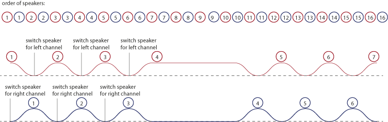
We have red speakers 1-16 for right channel and blue speakers 1-16 for left channel. In the following we focus on one channel, so that we can easily describe what’s happening:
- whenever you have reached volume 0 switch to the next (or previous) speaker
- fade in and then fade out again
Later (as you can also see in the image) we shift the channels: When left channel is high, right channel is low. So the sound is wandering from a left speaker to a right speaker, then to the next left speaker an so on. We are up and running.
Finding the path
Finding the path is one of the the crucial tasks in this programming. As you remember we are using many relays to connect the appropriate speaker to the amp. What finding the path now means is, that we have to tell the relays with status to take. Let’s consider one relays switching two speakers:
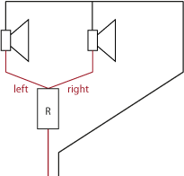
One channel consist of a cable with two wires. First wire we connect to both speakers. Second wire we will switch using a relay. If we command the relay to switch to “left” one speaker will play, if we command it to switch to “right”, the other one will play.
With multiple relays we need multiple commands. We now just replace “left” with 0 and “right” with 1 and connect two relays to the first one:
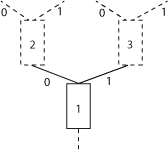
Here we could already switch 4 speakers and the “path” would be left-left (00) or left-right (01) or right-left (10) or right-right (11). You already get it. It is a binary system. A good example of just how easy (and close to all-day-problems like ours) binary systems can be. (We could also talk about a watering system for plants, where you guide a water flow multiple times left or right with multiple gates. It’s the same problem, but we’ll stick to speakers, I think it is nearly as easy to understand.)
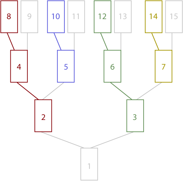
Let’s now draw the whole setting, complete with path examples and how to calculate speaker numbers from paths and the other way round:
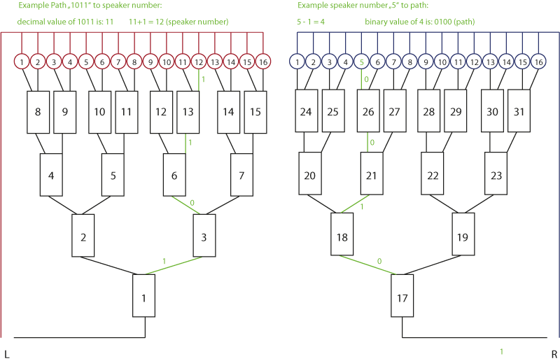
It’s very easy: The speaker number is the decimal (our “normal” numbers, based on the factor 10) representation of the binary number describing the path. Only starting with 0, so that we have to add 1 in case we want intuitively understandable numbers. See the examples in the image above.
What’s missing?
One thing is still missing, though: We now know the path but do not yet know which of the relays are to be switched. So for example path 1011 will lead us to speaker 12. We have to:
- switch relay 1 to right
- switch relay 3 to left
- switch relay 6 to right
- switch relay 13 to right
while path 0011 will lead us to speaker 4 but we have to:
- switch relay 1 to left
- switch relay 2 to left
- switch relay 4 to right
- switch relay 9 to right
Of course thins information is hidden in our setting: if we set the first relay to right, second number of the path will of course be referring to relay 3, whereas if we set the first relay to right to left, the second number of the path will be referring to relay 2. Just check the image and you see that it is obvious. We just have to find out how to do the math to get this information.
Let’s have a look at the path parts going left only:
2-4-8, 5-10, 3-6-12, 7-14… you see the pattern: Next relay number is double the actual relay number – in case the according path digit is 0 (left). In case the according path digit is 1 (right) same rule applies but the result is is incremented by 1 afterwards:
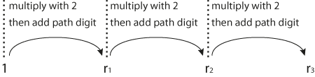
(Great thing here is, that we don’t have to worry about binary or decimal. This is a very special case, as we are only using 0 and 1. 0 is 0 and 1 is 1 both in binary and decimal system. Only from 2 (binary: 11) onwards we have to distinguish between the systems.)
We are ready!
So as soon we know which speaker we want to address, we can first calculate the path and then calculate which digit in the path is connected to which relay. So we know everything to switch the relays correctly.
In the next part, I will discuss the technology used, the communication between the used parts, and (shortly) the actual programming. Sorry, not yet online!